Within the CIE Computer Science A Level, whilst you are required to identify the use and general operation of a variety of hardware devices, there are several that you are required to understand in greater detail. We refer to discussing how these devices perform their primary tasks as the Principles of Operation.
As this topic contains a considerable amount of detail, the tabs below will help you to access the information about each hardware device individually.
Laser printers are used for high volumes of printing due to their speed and efficiency with toner. They are used in offices and schools as these are organisations where large volumes of text documents need to be printed. Whilst laser printers are initially expensive to purchase, their use of print media (toner) is efficient which makes them more cost efficient over a long period of time.
The majority of laser printers in most organisations are greyscale as colour toner is both expensive and the quality of images produced by laser printers is not particularly high, and are generally avoided for photographs.
Exam tip: When we talk about the principles of operation of a laser printer, the examiner will expect you to be able to describe how the printer goes from receiving a digital file to producing a physical item. The animation below shows each of the steps that you may need to describe:
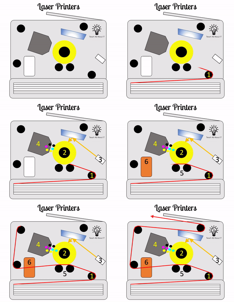
Laser printers create printed documents through rolling paper through a set of drums following these steps:
- Paper is picked up from the tray using a drum
- The paper is fed towards the main drum which holds a magnetic charge.
- A laser is then shone onto the drum in the pattern to be printed changing the charge
- Toner covers the drum and is attracted to the areas where the laser has changed the charge
- As the paper rolls past the drum, the ink is transferred onto the paper
- The paper is then fed through heated rollers, sealing the toner onto the paper
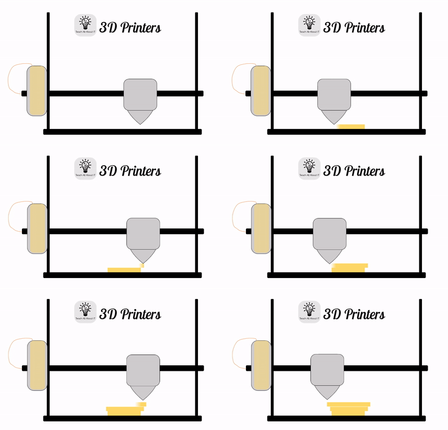
Unlike standard printers, 3D printers produce physical items that are made from an object model that has been split into layers, also known as Slicing. 3D printers are divided into two types:
Filament printers use a spool of material (usually plastic) which is fed through the print head into an extruder. The extruder is heated to melt the filament which is squeezed out as the print head moves to create a single layer of the print. The print section then moves up to allow for another layer to be printed in the same way.
Resin Printers also print in layers, but do this by dipping the print bed (and the printed model so far) into a bath of polymer resin and shining a laser in the shape of the layer from underneath. This laser cures the resin which sticks to the previous layer of the printed object. The print bed is then moved up to release the cured model from the bottom of the resin bath, and lowered again to create the next layer.
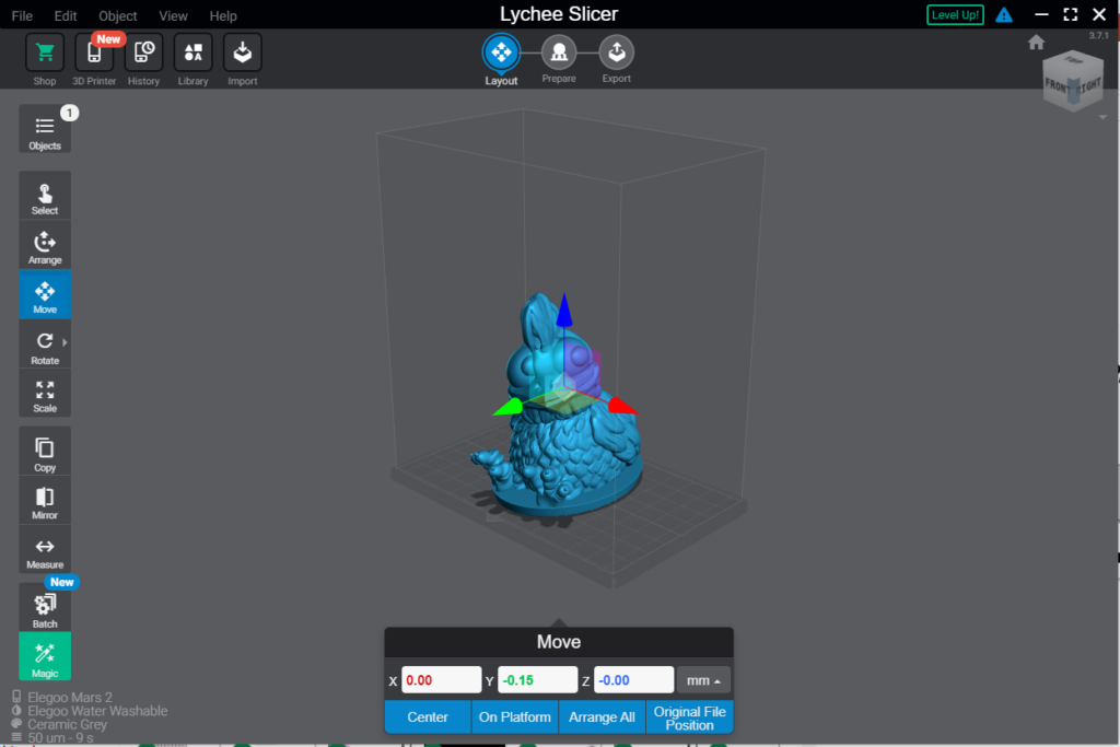
Before printing, objects must be designed in CAD (Computer Aided Design) software with measurements set for X, Y, and Z axis. This software allows the designer to make adjustments to the model and often see a preview of what the object may look like once printed. Often, separate software for 3D design and slicing is used to allow designers to work more accurately with specific printers.
Microphones maybe a standalone peripheral device or built into a different peripheral such as a headset. In whatever form they take a microphones job is to convert the analogue sound waves around it into digital data.
This conversion is performed using a component called the ADC or analogue to digital converter. The ADC measures the analogue sound waves amplitude at regular intervals, converts these measurements to binary, and saves this as digital data which can be later translated back into a sound wave using a speaker.
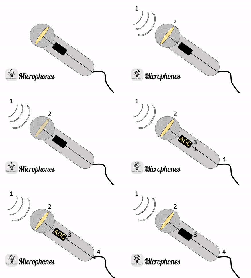
- Analogue sound waves reach the microphone
- A diaphram inside the microphone reacts to the analogue wave
- The vibrations of the diaphram are measured at regular intervals by the ADC
- These measurements are converted to binary and sent to the computer system as digital data
Much like microphones, speakers work with both digital and analogue data. Whether the speaker is part of a high quality sound system, or an in ear headphone the same principles will apply.
Speakers work in the opposite way to a microphone, by taking digital sound samples and converting these back into analogue sound waves that can be heard by the user.
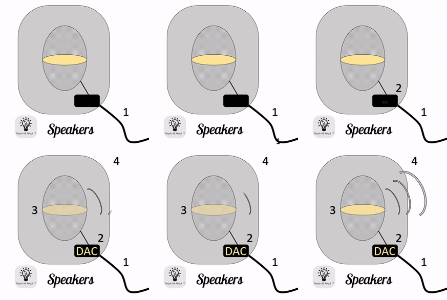
- Digital data is sent from the computer to the speaker – each binary number represents a sample (measurement) of the sound wave
- This is converted to an electrical impulse by the DAC (Digital to Analogue Converter)
- The signal is then sent to a diaphram which vibrates at the sound frequency of the sound sample
- The vibrations then create an analogue sound wave
Magnetic hard drives have been the standard for computer hard drives since the 1950s and store data in a state using magetic charges on a set of discs called platters.
The disc that you see inside a hard disk drive is heavily processed metal which have been developed to be easily magnetised and de-magnetised repeatedly.
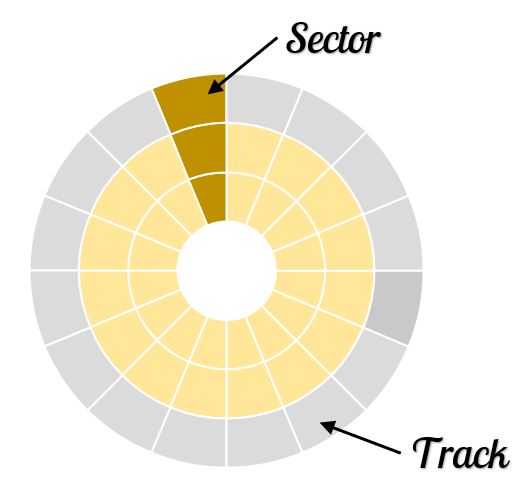
In order to store data in recognisable locations, the platter in the hard drive is organised into concentric circles called tracks from the inside of the disc to the outer edge, creating a spiral that the read arm can follow.
Within these tracks, triangluar slices of the disc are created to form smaller areas called sectors. These can be accessed as a whole sector of the disk which is the full “slice” from centre to the outside, or a track sector which is a single, smaller slice within the track. Each track sector is given an address to allow a File Allocation table to create a reference for where data is stored.
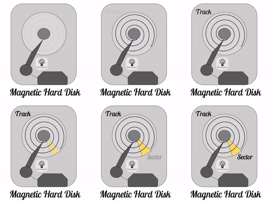
To read the data from the platter in the hard disk drive:
- The platter spins from the centre
- Then the read/write arm scans the platter for data based on positive / negative magnetic charge
To write to the disc, the same process is used, but the read/write arm uses an electromagnet in the top of the arm to place positive / negative magnetic charge onto the platter.
Solid State Drives are, as the name suggests, hard drives that are built on flash memory technology. This is often referred to as EEPROM, or Erasable Read only Memory and is found in a variety of solid state memory chips.
Within a solid state drive, data is saved as electronic signals inside transistors that have a layer of insulation to prevent data less when power is switched off (volatile memory such as RAM does not have this insulation and as such all transistor gates will retutn to 0 when power is off).
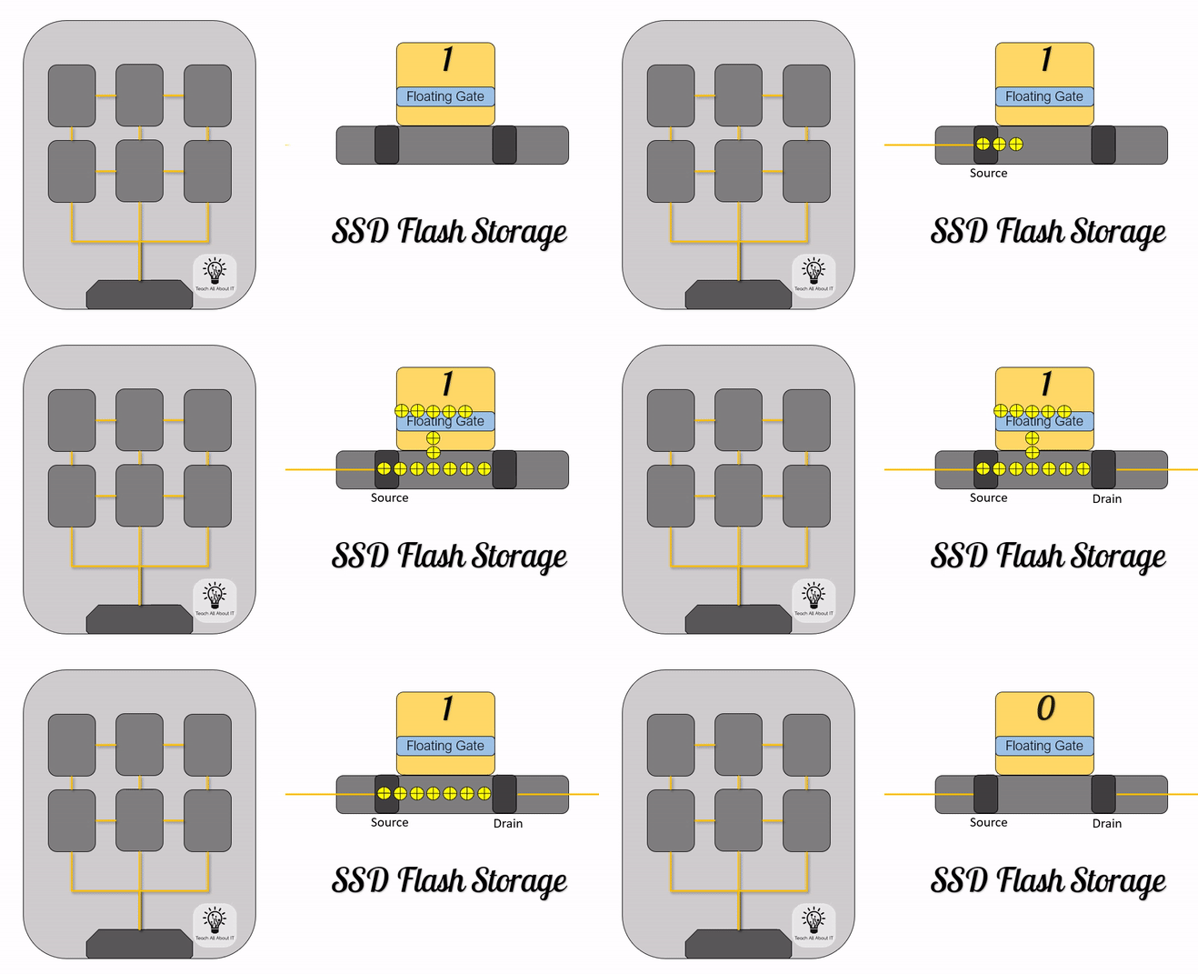
To store data inside a solid sate drive:
- An electrical current is sent to the transistor’s source
- The floating gate within the transistor captures the electrons
- The presence of these in the gate switches the gate to 1
- The Drain for the transistor allows the electrons for be released from the transistor
- The absence of electrons in the floating gate switched the gate back to 0
Optical discs can be described as “any disc that can be read using a laser”. These can generally be divided into CD, DVD, and BluRay.
Within the optical disc names, you may also see the letters -R, -ROM, and -RW after the name. This refers to what can be done with the disc:
| Postfix Letters | Disc Capability |
|---|---|
| R | Recordable This is a disc that can be written to, but only once |
| RW | Rewrite This is a disc that can be written to & overwritten multiple times |
| ROM | Read Only Memory This type of disc is generally used for distribution. It is written to during manufacture and cannot be overwritten. |
In a similar way to hard drive platters, optical discs store data in sections called tracks and sectors. However, instead of magnetising the disc, data is stored by creatinga difference in time when the read arm shines a laser onto the disc.
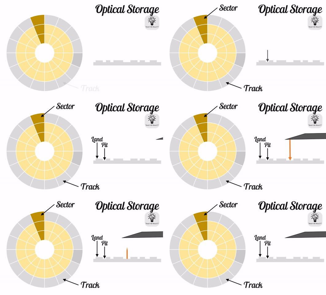
For discs using the -ROM or -R postfix, this is created by adding indents into the track called pits. This leaves areas that are slightly higher called lands. Although it is not possible to see these indents with the human eye (aside from a discoloration on the disk), this is enough to change the time that the light from the laser is returned to the read arm enough to create a series of physical representations of 1s & 0s.
For rewritable discs, this same difference in the time to return the light is created by using a higher powered laser to “burn” the lands into the disc. This creates darker areas on the disc using an ink that can be released or cleaned to create the binary data.
Touch screens come in two different formats: resistive and capacitive.
Resistive Touch Screens
The older of these is resistive and is often seen in older devices like PDAs or the original version of the Nintendo DS. A resistive touch screen requires the user to use a hard stylus or fingernail which touches 2 screens together creating an electrical connection which is measured using sensors around the edge of the screen. Resistive touch screens are often found where the screen needs to be tougher such as ticket machines in public places.
Capacitive Touch Screens
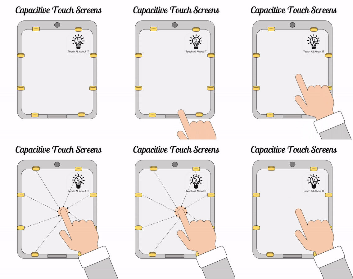
Capacitive touch screens require a conductive surface to touch the screen such as a fingertip and do not work with hard styluses and fingernails.
The capacitive screen uses this conductive surface to break the electrical signals that are being sent across the screen. Using similar sensors the place at which the touch screen was disrupted his measured. This more recent technology require a hard screen often using glass and is seen in most smart phones.
When considering the use of a touch screen in a given scenario, it is generally worth considering the user and environment around it.
In recent years, additional consideration is given to the use of touch screens for public devices as they may carry health risks. In these scenarios, considering the durability of a device when there is a need to clean surfaces is prudent. Where durability is a concern, the older, resitive screen may be more appropriate.
Unlike a simple screen, VR (Virtual Reality) headsets are a complex combination of inouts and outputs that allow the user to interact with software through natural human movements and “see” the virtal world around them.
VR Inputs
The movements in a VR headset make use of several sensors that you may be familiar with from other control systems:
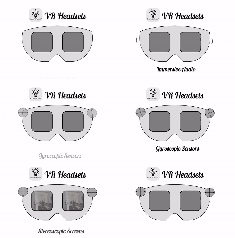
Gyroscopes are used to measure the angle and orientation of the headset (this is why VR images can seem offputting if the headset is not positioned correctly).
Accelerometers are then used to measure how fast the user is moving their head.
In combination, these are able to provide enough data to the computer system to adjust the image displayed to the user as if they were actually looking around in the digital scene.
VR Outputs
Although not built into every VR headset, most will include a form of immersive audio which makes use of 3D stereo sounds. This allows the user to hear the virtual world in the same way that they would the real world. This may be built directly into the headset, or more often played through headphones that are plugged into the device.
The most immersive feature of the VR headset is the use of stereoscopic lenses. Two separate screens are projected through fisheye lenses to mimic the 3D effect that we view the world in. By projecting the scene with a small adjustment for each eye, this fools the human brain into seeing a fully 3D image.
The concept of stereoscopic images to create 3D images is certainly not new. The image below is a 3D image of New York Harbour from 1858 and was designed to be viewed using a device called the Brewster stereoscope.

If you would like to read more about 3D imaging in the Victorian era, I highly recommend this blog from Oxford University Press.
